|
|
|
 |
| |
|
.jpg) |
|
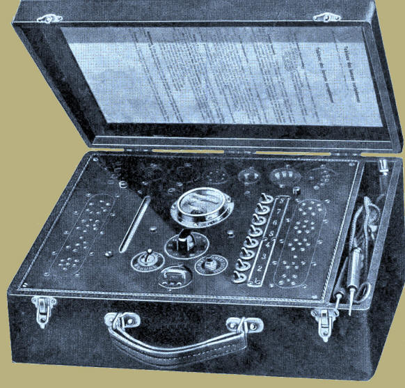
Lectern model in wooden suitcase, covered with
black leatherette. The
tester can be used for emission and leakage tests. Made by Télémesure
around 1939. The company was founded in 1932. In 1946 Télémesure
was taken over by Manufacture d'Appareil Radio-Électrique du
Rhône (MARER), 39 Route de Vaulx, Lyon-Villeurbanne. Télémesure
remained one of the brand names of MARER. Under this brand name
more measuring equipment was made. In 1945
they made the Radio-Test R4 voltmeter and the tube tester Major; in 1946
the valve tester L46 and in 1948 the L48A. |
 |
|
Description of the tube tester |
|
A position switch for the filament current is
located below the meter (scale 0-50 mA). Positions: 2, 2.5, 4,
5, 6.3, 7.5, 10, 13, 16, 20, 25 and 30 volts. |
| A switch with the text "Essai/Mesure"
is situated on the left of the position switch.
In the upper position, the filament can be tested, a
measurement can be performed with the switch in the
lower position. |
|
To the right of
the position
switch is
a push-button,
that can be used to insulate the
filament from
the cathode. |
|
Right below the position switch, test
leads and a jumper can be used.
The
two upper
contacts, labeled
"L",
can be used for a continuity test.The jumper in the middle is an interconnection for the
test voltage.
This connection can also be used to insert 70 volts DC for
measuring capacitors.
The
two
lower
contacts,
labeled "M", can be used for
leakage testing. The neon tube serves
as an indicator. |
|
The filaments connections are
hardwired;
the switches, numbered 1 to 8, can be used to convert a
measurement voltage of 110 volts on one of the other
tube pins.
Because the tube tester is only suitable for pre-war
tubes
with a maximum of 8 pins, only the first 6 switches are used.
Switch 7 switches the top connection (orange and black bus) and
the central pivot of a loctal tube. Switch 8 can be used in case of an extension. |
|
On the left and right there are two
strips with tube sockets, numbered from 1 to 9 (left:
1-4, 5-9 on the right), numbered from bottom to top.
Another row of tube sockets is situated at the top. The left
base could be used as extra, in this case a B7 base. |
| |
.jpg) |
Sockets |
| |
|
|
| Strips |
|
Upper row from
left to right |
| 1 |
B3/B4/B5/B6
|
B7 |
| 2 |
B5G, E34, O |
B8G (Loctal) |
| 3 |
B7B, Q* |
K8A, IO (International Octal) |
| 4 |
B/C |
Y8A, G8A |
| 5 |
UX4 |
P5, Ct5 |
| 6 |
UY5 |
P8A, Ct8 |
| 7 |
UX6 |
Mains selector: 110,
130, 150, 220 volts |
| 8 |
UX7 |
|
| 9 |
U7B |
|
|
*) e.g. for a DW1B or a TM4Q |
| Right of the left tube strip are two
indicators: green: filament ok, red: short circuit. |
| On the right of the indicator lamps
is a neon lamp with a printed scale (1-10). It serves as
an indicator tube for a leakage test. |
| Warning:
when the tube tester is connected to the mains, high voltages can be
present on the metal parts
or the metal
paint
of
the tube
that is being tested! |
|
|
|
d.jpg) |
|
Bottom of the chassis
plate |
|
 |
|
Picture from the user manual |
|
|