|
|
 |
| |
|
d.jpg) |
|
Description of the tester |
|
The tester is
housed in a
wooden case with leather handle, lined with
brown paper with leather print.
Black aluminum front plate with
white print. Suitable for the measurement of
emission of electron tubes and
the value of resistors and
capacitors.
The tester can alsio be used to measure voltages and currents.
Made by E.N.B.
(E.N.
Batlouni)
Laboratoire Industriel Radioélectrique, 25, rue Louis-Le-Grand,
Paris 2e. |
|
Left of
the meter with the indications "resistances" (0-10000 ~
Ω) and "capacités" (0-10 ~ uF) and the blue, white
and red markings
with the texts "mauvaise" (bad), "douteuse" (doubtful) and "bonne"
(good) is the switch for the
filament
current with the positions: 1.5 ∙ 2 ∙ 2.5 ∙ 4
∙ 5
∙ 6.3 ∙ 7.5
∙ 12 ∙ 20 ∙ 24 ∙ 30 and 40
volts. Above the
entrance of the power cord is
a jumper for
the AC voltage.
Bottom right is the on/off switch,
surmounted by a number of connections that can be used for
connecting a resistor or
a capacitor for testing. |
|
There are
25 tube sockets with a number of different versions of a single
tube type, such as the octal base, the UX7 base and the P-base. Sockets H and
Z were reserved for "future" tubes. This tester has the G8A/Y8A
base and an extra octal base. Below are 9 sockets that can be
used for manually connecting tubes via measuring cables. Socket
1 is used to connect the top connection of a tube; socket 0 is
used to connect the cathode and socket 6
is used for a possible 2nd
cathode. |
|
The tester
has an isolating transformer,
so that the metal parts or the metal paint of a tube can be
touched safely. |
|
The original price of the tester was Ffr 1475,- |
|
Filament, short circuit and emission test |
|
On the right of the meter
is a switch that can be used for the the different measurements.
The filament can be tested in position F, the electrodes
can be checked for short circuits in positions 1 - 6, the
emission can be determined in positions 7 -9 and
the cathode
can be isolated in position 0. |
|
Measuring resistors and capacitors |
|
In position M, the value of a capacitor (in
the range 0,1-10μF and 0,01-1μF) or a
resistance (in the range of up to 10,000Ω and
up to 100,000Ω) can be determined. When testing
resistors above 10000Ω the value should be
multiplied by 10; when testing capacitors in the range
0,01-1μF the value must be divided by 10. |
|
After the shorting plug "Cond.
Élec."
is removed, an electrolytic capacitor can be connected
between the terminals - and +. A working tube
must also be inserted in one of the sockets of the tester,
so a DC voltage is present. In this way, the
leak of this capacitor can be determined. The
dynamic behavior of the meter makes is
possible to see if a capacitor has a large capacity
or a smaller capacity. |
 |
|
Measurement of
voltages and currents |
|
When measuring
voltages and currents, the plug of the tester must be shorted.
The filament current switch must
be put at 1,5 V and the
measurement switch to M. Voltages up
to 20 V can now be measured by
connecting it at the two buses with
the inscription "10.000Ω-10uF". Voltages up to 60
volts are connected between the central
bus and the lower bus and voltages in the
range of 200 volts at the busses for
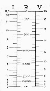
100.000Ω-1uF. When the reading the value, the IRV
list in the lid can be used. There is no multiplication
factor for 20 V, X 3 for 60 V and X 10 for 200
V. |
|
The measurement of
currents, is carried out in approximately the
same way. The current is applied to the buses for 10.000Ω-10uF.
Position 0 is used for the measurement of currents
larger than 12.5 mA. Currents up to 12.5 mA can be read
directly; in the highest position
the reading should be multiplied by 4. |
|
The tester was sold in 2021. |
.jpg)
|
The meter can be used for
measuring emission and for measuring
resistors and
capacitors. |
|
Tube sockets1 |
| A |
B3/B4/B5 |
J |
UY5 |
S |
K8A, IO
(International Octal) |
| B |
B3/B4/B5 |
K |
UY5 |
T |
K8A, IO
(International Octal) |
| C |
B5G, E34, O2 |
L |
UX4 |
U |
K8A, IO
(International Octal) |
| D |
B/C |
M |
UX6 |
V |
K8A, IO
(International Octal) |
| E |
P5, Ct5 |
N |
UX6 |
X |
K8A, IO
(International Octal) |
| F |
P8A, Ct8 |
O |
UX7 |
Y |
B8G
(Loctal) |
| G |
P8A, Ct8 |
P |
UX7 |
Z3 |
K8A, IO
(International Octal) |
| H3 |
Y8A, G8A |
Q |
UX7 |
|
|
| I |
B7 |
R |
UX7 |
|
|
|
1) see the user manual for a
list of tubes and sockets |
|
2) for instance a DW1B or a
TM4Q |
|
3) the bases H and Z
were reserved for "future" tubes |
|
|
|
d.jpg) |
|
Under-chassis view |
| The value of some carbon resistors
was customized by filing out a piece of carbon. |
|
|
 |
|
Advertisement for the tester in "Le
Haut-Parleur", 1941 |
|
|